Diagnostic Testing for Available Voltage on Circuits
This lesson is about the easiest and most important electrical diagnostic test you can perform. A voltage available test allows you to discover where voltage is present, how much voltage is present, and if your circuit is complete or not.
The first thing you will need is the proper tools for the job. There are several options out there for you to pick from. Each brand offers distinct advantages, and each tool type has it perks.
For this test, I have provided a compiled list of tools that you could will need, a short description of each one, and a link to buying one on Amazon. I have found that Amazon offers the best prices on about anything you may need for any project.
The Power Probe 3 - This is basically a logic probe, a voltmeter, and a jumper built into one. It will allow you to read voltage, find grounds, find power sources, and even apply power/ground to the circuit with a switch.
Digital Voltmeter - A meter that allows you to read voltage. Also come as a DVOM (digital volt and ohm meter). This test requires only the voltmeter function, but a DVOM is the best.
Test Light - Unfortunately, a test light can only tell you if you HAVE a power source or a common ground. I do not recommend using a test light because it does not tell you an actual voltage measurement, but works in a pinch.
Once you have picked up all of the necessary tools, you will need to understand a bit of basic knowledge about electricity. All terms can be defined in the Electrical Dictionary. Modern automobiles have 12V DC systems, with the exception of hybrids and electric cars. All references in this guide are for the 12V system.
There are several rules electricity must follow. Electrons and protons are not like people - they can not break or bend rules.
Electricity always takes the easiest path to ground. If it gets the opportunity to go straight to its destination (ground) it will ALWAYS in a flash - literally.
If power flows to ground without first passing through a load, then we declare it shorted. Direct shorts are basically like putting a wrench across the battery terminals. If the circuit is fused, it will certainly blow the fuse. If it has no fuse (like a wrench), it will melt the wire, cause a fire, or potentially blow up the battery.
A rule you should be familiar with... DC voltage will always be the same as source voltage throughout the whole connected part of a open circuit. Assuming the break is after the load, voltage measured after a load in a open circuit will still read source voltage.
Voltage read after a load in a closed circuit will always read less than original voltage. How much less is determined by how many loads, type of circuit configuration, and how much resistance each load including wire. Ohms Law will explain the rest of that to you.
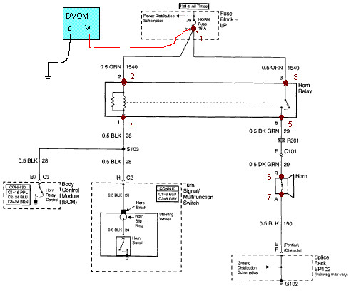
Here is a simple horn circuit from a GM from Alldata. Alldata is a paid professional program used by technicians to get detailed knowledge about anything on a particular car, basically a sophisticated service manual. Alldata does offer some home user plans as well.
In this circuit, I will describe how to test for available voltage, why to test there, what results to expect, and an explanation of what the results infer. This part may be a bit complicated for some, but it is much easier to describe where and how to test using a real life circuit.
- The first step in ANY diagnosis is to verify the customers complaint. If the customer says "My horn does not work" then you should try the horn first. This often prevents customer miscommunication.
- Note how the positive lead is placed onto the fuse terminal and the negative lead is placed on a common ground or the negative terminal on the battery. All voltage available tests are done in this manner. Keep the tester grounded and only move the positive lead from point to point. The Power Probe 3 allows you to hook a positive and negative to the battery to test that on the fly.
- If the horn does not work, you should then test the easiest component next.. the fuse. The diagram provides the example of how to test available voltage after the fuse on this circuit (point 1). During this test, you would expect to get a reading of 12V on a good circuit. If you do not have 12V, you should check the fuse itself and the power before the fuse.
- Next is to test voltage at point 2 and 3 at the relay terminals. The relay diagram is usually on the back of the relay. Those pins should match those of your diagram. You first have to remove the relay to test at the terminals or install a relay tester kit.You should have 12V in a good circuit. If not, you have a problem in the wiring between the fuse and the relay.
- You will only have a ground at point 4 if you activate the horn switch, otherwise your reading will be nothing with the relay removed. Point 5 should always be ground until the circuit activates the relay. Once the relay is activated (by grounding point 4 with the relay plugged in or by using the horn switch) it will complete the circuit to the horn. You should have voltage on points 5 and 6 once it is active. If you do not, check the relay for a problem.
- Point 7 will be a ground regardless if circuit is open or closed. If you have 12V here, check your ground for a loose or bad connection.
- What if you have power at point 6, ground at point 7, and your horn still doesn't work? Sounds like you need a new horn.
- A good way to check ground is to test from point 7 to chassis ground. Should read zero.
- Be Careful to not to accidentally apply power to the control side of the circuit. The control side is the part of the relay on the bottom left hand side of the diagram. Applying power here could damage the connected turn signal switch assembly or even the BCM.
Now lets review what we have done. Every voltage test you performed is a Voltage Available test. Available voltage tests can tell you exactly where power is located at, home much power is available at any given time in the circuit, and if you have a good ground circuit. Just remember that anytime you are testing a circuit for voltage available you must always set up the tool in ;parallel to the current circuit, otherwise you defeat the purpose of the test.
Don't forget to check out my other articles. The next article after this one should be about how to test Voltage Drop.